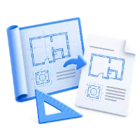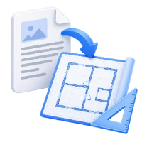

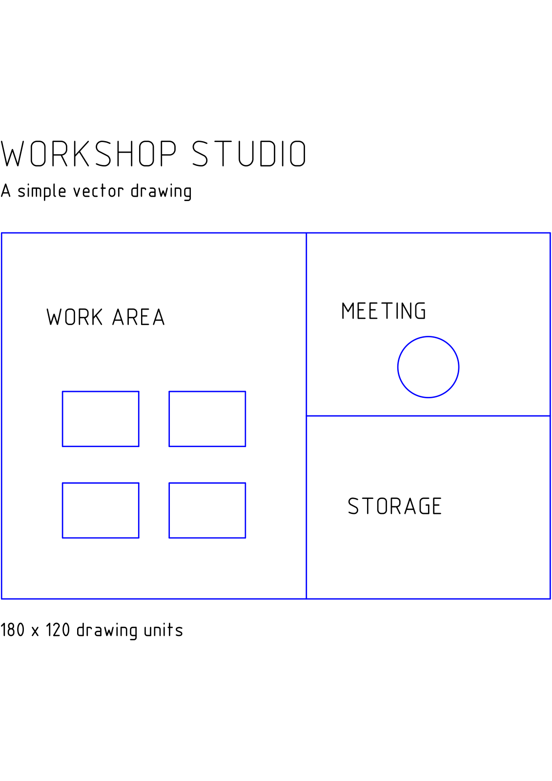
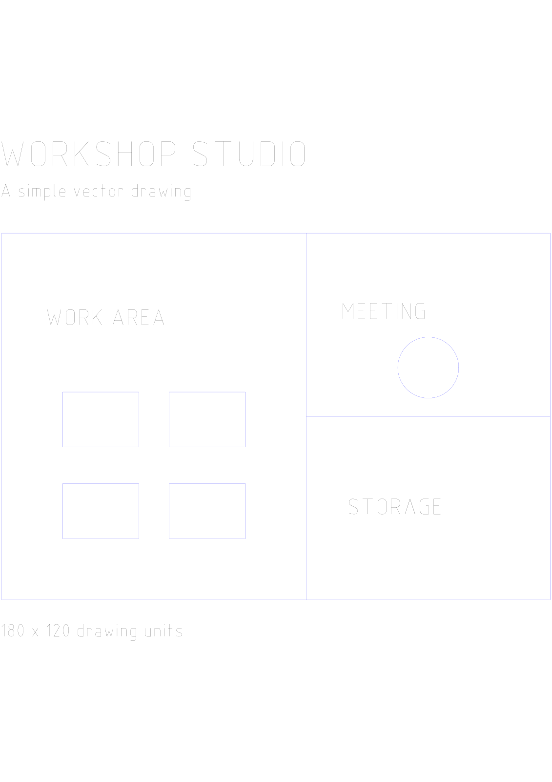

Open PDF to CAD, add a PDF and choose the pages to convert. Our example starts with a one-page vector drawing of a workshop studio and produces one DWG file.
Choose a suitable source PDF
Add the PDF and check the page preview. A drawing containing vector lines and shapes is the appropriate starting point for editable CAD geometry. A scanned plan contains pixels and may need a separate tracing workflow.
The example contains room outlines, work tables and a meeting area. Keep the source PDF available for comparison after importing the result into your CAD application.
Set the pages and output
CAD format offers DWG and DXF. Our example keeps DWG. Choose DXF when that is the exchange format required by the receiving application.
Leave the page range blank for all pages or enter the pages you need, then choose Start. The example uses its single page.
Download and inspect the CAD file
Download the result. One selected page produces one DWG file; multiple pages produce a ZIP containing separate drawings. Extract the archive before opening those files.
Open the drawing in your CAD program and compare important lines, dimensions and text with the PDF. Verify a known dimension and the drawing units before using the geometry in another design.
Common questions
Which CAD format should I choose?
Use the format requested by your collaborator or CAD application. This tool supports DWG and DXF; check compatibility in the receiving program.
Will the drawing automatically have the correct real-world scale?
Do not assume that it will. PDF page dimensions and CAD units are different concepts. Check a known dimension and adjust the drawing’s units or scale in your CAD application when necessary.
Try it with your document
Review the result, then save the version you need.